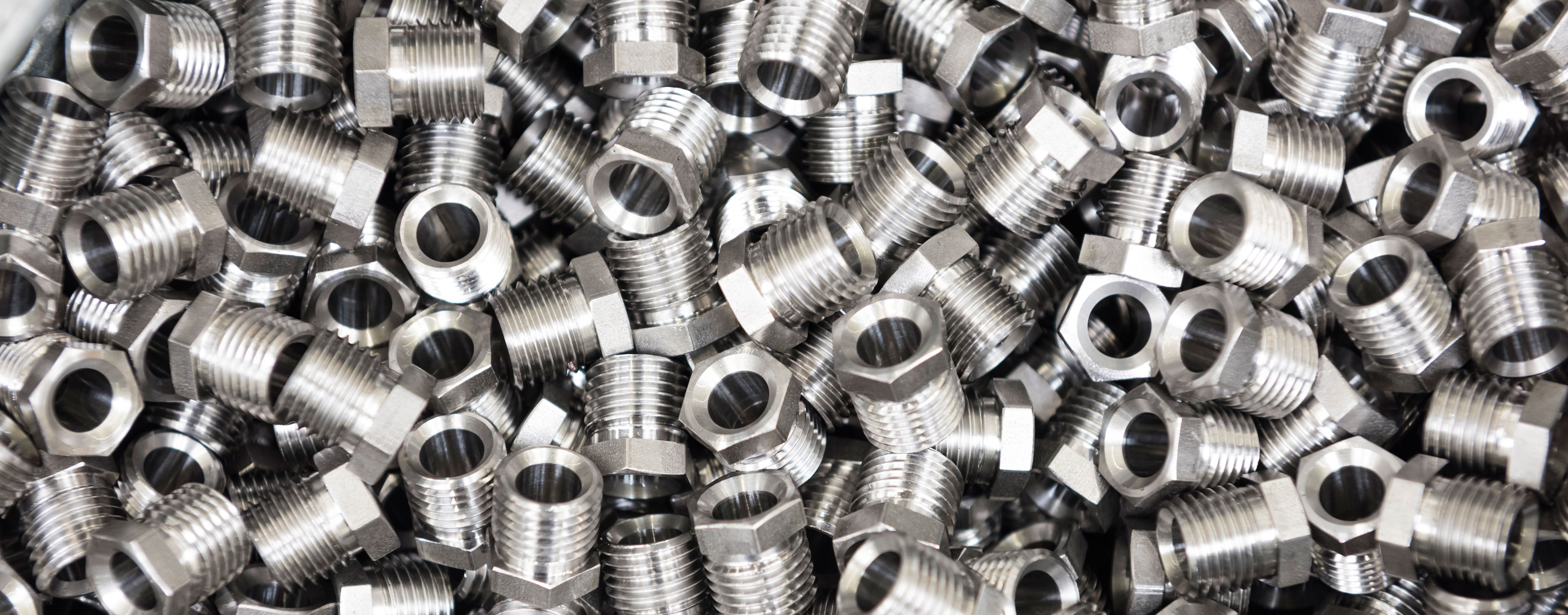
Portfolio for standard parts, drawing parts & CNC turned parts
Precision, speed and cost-effectiveness
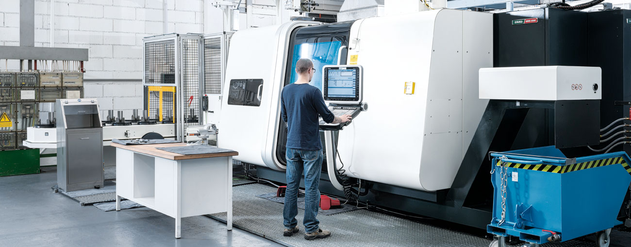
Machine pool
- Innovative technology: One of the industry's most modern machine pools enables fast, flexible and competent responses – even for challenging delivery deadlines.
- Rotary transfer production technology: Continuous production flow: uninterrupted processing from raw material to finished product.
- CNC technology: Manufacturing in various performance classes, bar-fed, precise and cost-efficient to meet individual requirements.
- Process optimization: Versatile machine concept for everything from simple components to geometrically complex parts.
- Tool management: Fully automated machine and tool management with continuous, documented quality monitoring.
Material & Surface
- Raw material: Undercut steel as well as stainless steel in A2 and A4 quality, stocked proactively to ensure maximum availability.
- Material diversity: In addition, special steel grades with corrosion-resistant, seawater-resistant, as well as heat- or high-strength properties.
- Surface coating: Numerous electroplated and mechanical coatings – tailored to the material and geometry.
- Surface treatment: State-of-the-art cleaning – available degreased (oil-free) or with a defined oil film.
- Surface heat treatment/finishing: In cooperation with strong partners: grinding, hardening, nitrocarburizing and much more.
Quality
- ISO certification: Strict quality criteria according to DIN EN ISO 9001:2015 – no product leaves the premises without inspection.
- Continuous quality management: Standardized monitoring from receipt of raw materials to delivery of the finished product to ensure high process reliability.
- Commitment to quality: The best possible quality in all areas of the business relationship – far beyond the product itself.
Service
- Full Service: Manufacture of complete assemblies, including assembly, packaging, labelling and stocking according to specifications.
- Logistics management: Forecast-based availability of market-standard products as well as tailor-made logistics solutions.
- Webshop: 24/7 access to proven quality products and services — quickly and efficiently to the desired item.
- Technical documentation: Initial sample reports, FMEAs, test reports, tensile tests up to SPC analyses.
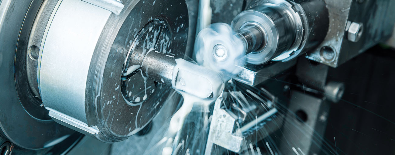
Metal processing
- Precision parts: Thanks to more than 50 years of experience as a manufacturer, mbo Osswald knows what matters when it comes to precision parts. Therefore, in addition to an extensive standard range, mbo Osswald also manufactures individual custom-made parts exactly to your specifications — with the highest precision and reproducible dimensional accuracy.
- Range of services: mbo Osswald's range of services includes the production of turned parts from bar stock with diameters from ø 4 to 65 mm and lengths up to 350 mm. Cross-drilling, slotting, milling, polygon turning as well as complex geometries are implemented by mbo Osswald in a process-reliable, precise and economical manner.
Procuct development
- From idea to realization: Whether with clearly defined specifications or initially only a rough task – mbo Osswald supports projects from the first idea to series-ready implementation. It makes no difference whether a single, comparatively simple turned part or a complex assembly is to be produced: mbo Osswald’s development specialists analyze requirements, optimize designs and develop sophisticated, manufacturable solutions that are technically convincing and economically feasible.
Machining technology plays a central role in manufacturing engineering by selectively removing material from workpieces to produce specific shapes and dimensions. These processes are crucial for the production of precise components and encompass a variety of techniques tailored to the intended application and the material to be machined.
The aspect of precision is paramount here to ensure that the manufactured parts are both dimensionally accurate and exhibit an excellent surface quality.
Main machining processes
1. Turning
Turning
Turning is a fundamental machining process in which a workpiece rotates around its own axis while a stationary tool removes material to achieve specific shapes and precision. This process is particularly suitable for machining rotationally symmetric parts such as shafts and bolts. Different types of turning, such as longitudinal turning, facing and profile turning, enable the production of a variety of contours and threads.
The use of CNC technology has significantly improved the precision and efficiency of the turning process, which is especially advantageous in series production. Selecting appropriate cutting parameters, such as cutting speed and feed, is crucial for the quality and cost-effectiveness of the process. Overall, turning offers high flexibility and precision in the manufacture of complex geometric shapes.
Distinction between external turning and internal turning:
Depending on where the machining area is located on the workpiece, it is called external turning or internal turning:
- External turning: Refers to removing material from the external surface of a workpiece to bring it to the desired diameter.
- Internal turning: Refers to machining internal surfaces, e.g. in bores or recesses, to create internal contours.
Internal turning has some particularities compared with conventional external turning. While the surface to be machined in external turning is bent away from the tool, it is bent toward the tool in internal turning. This results in a larger shear angle, from which a larger cutting force follows. Because the tools used are usually very long and cantilevered, they are more prone to vibrations and deflection. This leads to poorer surface finish and dimensional accuracy. Chip evacuation is also problematic. Normally the chips are flushed out with the cutting fluid, which is pumped into the bore at high pressure. The BTA drilling method uses a similar technique for chip removal.
Groove:
Grooving is a special machining technique in turning used to make targeted shape changes to a workpiece. In this process, a cutting tool is plunged radially into the rotating workpiece to produce grooves, shoulders, or specific form elements.
This technique is essential for manufacturing components that require precise fits, guides, or locking functions.
- Features and advantages of the groove:
- Precision: The groove allows the creation of precisely defined slots with tight tolerances, which is essential for applications requiring exact fits.
- Versatility: The groove can be used to produce a variety of geometric shapes, including complex profiles and deep cuts.
- Efficiency: Grooving operations are relatively fast and can be carried out in a single machining step, reducing manufacturing time.
- Types of groove:
- Axial grooves: Also known as face grooves, these are worked into the end of a workpiece. This type of cut is frequently used to create mating surfaces, shoulders or steps. Axial grooves are typically used in the manufacture of flanges or partitions.
- Radial grooves: Here the cutting tool is introduced radially from the outside into the workpiece. Radial grooves are suitable for producing O-ring grooves or sealing grooves. A common application is the trimming of materials or the creation of retaining rings.
- Profile grooves: These combine various geometries and can include both axial and radial elements. Profile grooves are used to produce complex profile shapes or retaining grooves in a single operation. They are widely used in the manufacture of fasteners and special machine components.
- Use of the groove:
- Manufacture of retaining grooves: Grooves are used to produce grooves in shafts or bushings for retaining rings that absorb or limit axial movement.
- Shaping for seals: Radial grooves create grooves that can securely house and seal O-rings, which is why they are commonly used in hydraulics and pneumatics.
- Fits and supports: By making targeted grooves, components can be shaped so they fit precisely into other parts. This is particularly important for bearing surfaces or shoulders on shafts.
- Decorative or functional contours: In certain applications, grooves are also used to create aesthetic features or easy-to-grip surfaces for everyday use.
- Features and advantages of the groove:
Multi-sided machining:
Multi-sided machining is a specialized cutting process in which material is removed simultaneously by multiple cutting edges on rotating workpieces. This technique is primarily used to produce polygonal surfaces or special multi-edged profiles on a workpiece. In this process the workpiece rotates while a tool with multiple cutting edges comes into contact with its surface. The precise synchronization of workpiece and tool movements enables efficient machining of complex shapes and profiles that would be difficult to achieve with conventional turning methods. Multi-sided machining offers the advantages of high machining speed and accuracy, thereby optimizing the production of components with specific geometric requirements.
- Spanner surface:
A spanner surface is a precisely machined surface on screws, bolts, nuts and other fasteners. These surfaces allow tools such as wrenches, pliers or similar tools to be applied in order to transmit torque efficiently and to securely fasten or loosen the fasteners. Spanner surfaces are crucial for the handling and function of such mechanical parts, as they optimise the applied force and increase assembly efficiency.
- Properties of spanner surfaces:
- Shape and geometry: Spanner surfaces are usually flat, but typically formed as hexagonal or square to ensure optimal torque transmission. The most common shapes are hexagonal and square spanner surfaces.
- Size: The size of the spanner surface is generally specified by the nominal wrench size (e.g. SW13 for 13 mm), which makes it easier to select the appropriate tools.
- Material thickness and surface hardness: Since spanner surfaces are exposed to high stresses when tightening or loosening threaded connections, they are typically hardened or made from high-quality material to prevent deformation or damage.
- Properties of spanner surfaces:
- Square:
A square denotes a geometric shape with four sides of equal length and right angles. In mechanical applications, the term "square" refers to a square cross-section that plays a special role in the machining of workpieces. Square cross-sections are frequently used in the manufacture of drive or connecting elements because they offer specific functional advantages.
- Characteristics and advantages of the square:
- Geometric stability: The square cross-section offers high torsional strength, making it ideal for applications that require high torques.
- Simple drive member: Square profiles are often used as drive members in tools and machines, because their shape ensures simple and effective power transmission.
- Versatility: The square profile is versatile and available in numerous variations and sizes, allowing adaptation to specific technological requirements.
- Characteristics and advantages of the square:
- Spanner surface:
Thread:
- Female thread:
A female thread is a screw-receiving structure cut inside a bore and into which a male thread can be screwed. Female threads are designed to secure and position fasteners. They are indispensable in many technical applications because they provide a solid and precise connection between different components.
- Properties of female threads:
- Profile shape: The thread profile is generally triangular, as with the most commonly used metric ISO threads. However, there are also numerous other profile forms such as trapezoidal threads or inch threads (Whitworth or UN threads).
- Pitch: The pitch denotes the axial distance between two consecutive thread turns. It can be coarse or fine, depending on the application and the desired properties of the connection.
- Nominal size: The nominal size of a female thread refers to the internal diameter of the thread, which is decisive for the fit with a male thread.
- Possible applications:
Female threads are frequently used in designs where a detachable connection is required, but which must also transmit high forces when needed.
They are used in:- In the mechanical and plant engineering industry: They are essential for the design of machine components that need to be assembled or disassembled regularly.
- In electrical engineering: Enclosures secured by screws use female threads to allow access to electronic components.
- For consumer goods: Furniture, household appliances and sports equipment use female threads for secure yet removable assembly of individual parts.
- Manufacturing process:
Female threads can be produced by various processes:
- Thread tapping: In this process, a tap is used to cut a thread into a pre-drilled, smooth hole.
- Thread milling: A more precise method that is also suitable for large diameters and for materials with difficult chip formation.
- Thread forming: Here the material is displaced by a forming process rather than cut, which leads to a higher strength of the thread.
- Cross-industry relevance:
Female threads are indispensable in numerous industries because they provide secure and flexible assembly options. In the field of manufacturing technology, they enable the adjustment and replacement of parts, which is crucial for maintenance and repair processes.
- Properties of female threads:
- Male thread:
A male thread is a helical grooved pattern cut or formed along the external surface of a cylindrical workpiece. It is screwed into a corresponding female thread and serves as an essential component for creating removable connections. Male threads are widespread and play a crucial role in mechanics and engineering.
- Properties of male threads:
- Profile shape: As with female threads, the profile of an male thread is generally triangular (metric ISO thread), although there are other forms such as trapezoidal or inch threads.
- Pitch: The pitch of the male thread also determines the axial distance between two successive thread turns and varies from coarse to fine depending on the application.
- Diameter: The external diameter is the key dimension that determines the size and fit of the thread. It is the largest diameter of the thread and is crucial for compatibility with the corresponding female thread.
- Possible applications:
Male threads are used in numerous applications that require secure yet easily releasable connections. Typical application areas are:
- Mechanical engineering: Manufacturing of screws, bolts and other fasteners that secure machine components.
- Vehicle construction: Use in various vehicle parts that require regular maintenance or replacement.
- Construction: Connections in steel structures or in the fastening of building components with screws and threaded rods.
- Manufacturing process:
Male threads can be produced by various processes:
- Thread turning: In this process, the thread is cut into the workpiece using lathes.
- Thread rolling: This is a forming process in which the material is pressed into the shape of the thread by pressure, which can increase the strength of the thread.
- Cutting with a thread-cutting tool: A commonly used method in which the thread is formed by cutting away material.
- Cross-industry relevance:
Male threads are an integral part of many industries, as they provide the basis for versatile connection options. They allow the construction of robust, removable, and adaptable structural components, which is particularly important for ongoing maintenance and assembly processes.
- Properties of male threads:
- Metric / Inch:
Refers to the unit of measurement or the standard size of the thread. Metric threads are specified in millimeters, while inch threads are specified in inches. These types of threads are available to meet a wide range of international requirements. Metric threads are primarily common in Europe and Asia, while inch threads are mainly used in the USA and the United Kingdom.
- Right-hand thread / Left-hand thread:
Two basic types are right-hand and left-hand threads, which differ in the direction of rotation when tightening or loosening screws and nuts.
- Right-hand thread:
Right-hand threads are the most commonly used thread form. With them, the screw or nut is tightened by turning clockwise (to the right). The advantages and typical applications of right-hand threads are:
- Standardization: Right-hand threads are standardized worldwide and are used in most technical and mechanical applications, which makes their selection, handling and processing straightforward.
- Universal use: From household appliances to automotive parts and large mechanical engineering applications – right-hand threads cover a wide range of uses.
- Ergonomics: Since the majority of the world's population is right-handed, the clockwise tightening torque corresponds to the natural direction of movement, which facilitates assembly.
- Left-hand thread:
Left-hand threads differ in their direction of rotation: they are tightened by turning counterclockwise (left-turning). Their specific applications and advantages are:
- Specific application areas: Left-hand threads are often used where rightward-rotating movements occur that could generate an unscrewing torque, for example on rotating machine parts or on pneumatic fittings.
- Safety and prevention of loosening: On rotating parts such as fan blades or wheel nuts on the left-hand side of a vehicle, using a left-hand thread can prevent connections from loosening due to operational rotation.
- Identification of special function: In cases where a distinctive identification of the direction of rotation is required, such as on fire hydrants or gas cylinder valves to prevent accidental opening, left-hand threads are often used.
- Right-hand thread:
- Regular thread / fine-pitch thread:
The two most common types in mechanical engineering are regular threads and fine-pitch threads, which are each used in different applications because of their specific characteristics and advantages.
- Regular thread:
Regular threads, also known as standard threads, are characterized by their standardized profile dimensions and pitches. These standards allow for widespread and uniform use in many areas of engineering and industry. The most important characteristics are:
- Standardization: Regular threads are standardized according to international norms (e.g., DIN, ISO), which ensures their interoperability across a wide range of applications.
- Use: They are used in general industrial machinery, structural components, and everyday products due to their straightforward manufacturing and their adequate load-bearing capacity in many standard situations.
- Properties: Because of a larger pitch, i.e. the distance between thread turns, standard threads are easier to produce and enable faster assembly and disassembly processes.
- Fine-pitch thread:
Fine-pitch threads have a smaller pitch, which means that the thread turns are closer together. This special characteristic offers some outstanding advantages:
- Higher strength: Due to the finer thread profile, forces are distributed more evenly, allowing for higher axial and radial load capacity. Thus, fine-pitch threads are ideal for applications that require greater stability.
- Improved sealing: The finer thread structure provides better sealing at connection points. Therefore, fine-pitch threads are preferred in applications that must maintain high tightness against liquids or gases, such as in hydraulics or pneumatics.
- Precise adjustment: Since the distance per revolution is shorter with fine-pitch threads, they enable precise adjustment operations, which is particularly relevant in precision mechanics, instruments, or adjustable components.
- Regular thread:
- Female thread:
Roughing and finishing:
As with other machining processes, turning can also be divided into roughing (coarse machining) and finishing (fine machining). In roughing, significantly more volume is removed per unit of time than in finishing, and consequently high depths of cut and feed rates are used. The machining forces are high, and the resulting accuracy and surface quality play a subordinate role. The turned part is brought approximately to size. In the subsequent finishing, however, the desired final dimension of the workpiece is achieved. The machining forces are lower because the feed rates and depths of cut are smaller. The requirements for dimensional accuracy and surface quality are, however, higher.
Screw drive:
- External hexagon:
The external hex is characterized by its hexagonal head, which allows for effective transmission of force. This feature makes fastening and loosening screws with standard tools such as hex wrenches or socket wrenches easier. The external hex is one of the most common screw drives and is used in numerous applications that require reliable and simple connections.
- Features:
- Compatibility: Hexagon head screws are widely used and compatible with a variety of tools, supporting their universal application in various technical and industrial fields.
- Load capacity: Due to the even distribution of force across the six faces of the screw head, hexagon head screws offer high load-bearing capacity and torque resistance, making them ideal for applications with high mechanical demands.
- Practicality: The external hex allows quick and easy assembly and disassembly, even when access to the screw head is limited. This saves time and eases maintenance work in industrial environments.
- Features:
- Internal hexagon:
The internal hex is characterized by its hexagonal recess in the screw head, which enables efficient transmission of force using specialized tools such as Allen keys.
The internal hex, also known as the Allen screw drive, is a widely used choice for connections that require a flat and elegant finish.- Features:
- Space-saving: Hex socket screws provide a flush surface, since the drive is integrated into the screw head. This makes them ideal for applications where a smooth surface is desired or where there is little room for protruding heads.
- Stability: The hex socket allows secure transmission of force, which, due to the even distribution across the various contact points, ensures high stability. This is particularly advantageous in applications with limited access.
- Aesthetics: The flat design of hex socket screws contributes to a clean, attractive appearance, especially in applications where design matters, such as furniture or electronic devices.
- Features:
- Slot:
Slotted screws are characterized by a simple, straight slot in the screw head that allows torque to be applied with slotted screwdrivers. The slotted drive is one of the oldest and best-known types of screw drives, used in applications where simple tools and minimalist designs are preferred.
- Features:
- Simple handling: The simple design of the slot makes slotted screws easy to operate with conventional screwdrivers, making them versatile and accessible, especially in applications with low torque or precision requirements.
- Cost-effectiveness: Due to simple manufacturing techniques, slotted screws are often less expensive, making them a suitable choice for mass production and applications where cost is an important factor.
- Limited stability: However, the reduced contact area compared with other drive types can lead to an increased risk of cam-out or damage to the screw head, so slotted screws should generally be used in lower-stress applications.
- Features:
- Cross slot:
Cross-recess screws are characterized by their cross-shaped recess in the screw head, which was developed to reduce tool slipping and to ensure better centering. The cross-recess drive is an improved variant of the traditional slotted drive and is used in a variety of applications that require both ease of use and improved torque transmission.
- Features:
- Efficient torque transfer: The cross-shaped design provides multiple contact points for the screwdriver, enabling a more effective distribution of forces and increasing stability during fastening.
- Widespread use: Due to their practical advantages, cross-head screws are widely used across many areas, including electronics, furniture construction, and general household assembly.
- Improved control: The ability to apply higher torque without significantly increasing the risk of over-tightening makes cross-head screws ideal for applications that require more precise control.
- Features:
- Internal six-lobed (6-lobe):
Internal six-lobe screws are characterized by the star-shaped, notched recess in the screw head, which is specifically designed to ensure uniform force transmission and a secure connection. The internal six-lobe drive, or 6-lobe drive, provides a state-of-the-art fastening solution for applications that require increased stability and high torque.
- Features:
- High torque transmission: The unique shape of the 6-lobe profile enables efficient torque transfer with a reduced risk of the tool slipping, which promotes the longevity of the screw head.
- Minimized wear: The 6-lobe drive design reduces the likelihood of damage to both the tool and the screw itself, making it the ideal choice for professional applications that require repeated use.
- Versatility: Internal six-lobe screws are widely used across industrial applications, from the automotive industry to electronics, as they provide high reliability and safety.
- Features:
- External hexagon:
Knurling:
Knurling is a mechanical machining process in which a knurled, i.e. textured, surface is applied to workpieces. This process is often used to improve the grip and handling of components, whether for manual or machine applications. Using special knurling tools - e.g. transverse knurl (straight lines parallel to the axis), longitudinal knurl (straight lines across the axis) and diagonal or cross knurl (diamond-shaped patterns) - a regular pattern is produced on the surface of the workpiece. The most common patterns are straight lines, cross knurls and diamonds.
- Features:
- Process: In knurling, the knurling tool is pressed under pressure against the rotating workpiece. The rotating surface adopts the tool's pattern and thus creates the desired texture. This process can be applied to both metals and plastics.
- Flexibility: Different knurling patterns can be produced to meet specific functional requirements, such as facilitating the adjustment of a control element or increasing friction for particular applications. The choice of knurling pattern often depends on the intended use and the aesthetic requirements.
- Applications: Knurling is frequently used on the grip areas of tools, instruments, and control elements to improve grip and prevent slipping. This is particularly valuable in sectors that require precise work, such as precision engineering and medicine.
- Aesthetics and Functionality: In addition to functional improvements, knurling also offers aesthetic advantages, as the textured surface can enhance the visual appearance of products. This combination of function and design makes it a versatile technique in product design.
- Advantages: Knurling not only improves functionality in terms of grip and tactile feel, but also provides a fast and cost-effective way to produce decorative surface textures. It enhances both the ergonomic properties and the visual design of products.
- Features:
2. Drilling
Drilling
Drilling is another machining process in which a rotating cutting spindle produces a hole in a workpiece. It is often used to prepare other machining steps or to create connection holes.
Through holes / cross holes:
Through holes are holes that pass completely through the workpiece, whereas cross holes cross the workpiece and can connect to other previously made holes. Through holes and cross holes play an important role in manufacturing technology, particularly in joining and fitting components. Both types of holes have specific functional purposes and manufacturing processes.
- Through holes:
A through hole is a hole that passes completely through the workpiece from one side to the other. This type of hole is commonly used to accommodate screws or bolts that are intended to join two or more components.
- Manufacturing process: Through holes are typically produced using drill presses, milling machines, or CNC machines. The exact positioning and diameter of the hole must be maintained precisely to ensure correct fit and function.
- Applications: Common applications of through holes are found in mechanical engineering and metalworking, where they are used to connect components or to route cables and wiring.
- Cross holes:
Cross holes are holes that run laterally or across another structure, such as a shaft or a pipe. They are often used to create transverse connections or to direct liquid or air flows within a system.
- Manufacturing process: The production of cross holes requires particular care, as the hole must be introduced into the workpiece at a specific angle. Special drilling fixtures or five-axis CNC machines are often used for this purpose to ensure precision.
- Applications: Cross holes are widely used in hydraulics and pneumatics, where they serve as channels for the flow of liquids or gases. They are also used in machine assembly and in vehicle construction to secure moving parts or to connect components.
- Through holes:
Blind holes:
Blind holes are drill holes that, unlike through holes, do not pass completely through the workpiece. They end at a specific depth within the material. Blind holes are frequently used to fasten components flush with the surface without an opening being visible on the opposite side of the workpiece. This type of hole offers the advantage of ensuring a clean and aesthetically pleasing surface while preserving the structural integrity of the part. General characteristics of blind holes are the defined depth and the precise positioning within the material. They also provide the possibility of cutting threads to receive screws or bolts. Thus they are often employed where a fastening or connection is required without penetrating the entire component.
- Manufacturing process: The production of blind holes is generally carried out using drilling machines, milling machines or CNC machines. During manufacturing, particular attention must be paid to precise control of the drilling depth in order to reach the specified depth exactly without drilling through the workpiece. A depth stop device or a CNC control is often used for this purpose. Careful selection of cutting speeds and feed rates is necessary to ensure a high surface finish and precision.
- Applications: In mechanical engineering they are frequently used for tapping threads to enable screw connections where no bolt ends should be visible. In electronics, blind holes are used to fasten components to printed circuit boards without the holes penetrating the entire board. Another example is furniture making, where blind holes are widely used to create concealed joints that provide structural stability without compromising the external aesthetics. They are indispensable in any industry that values precision, functionality and aesthetic requirements.
Threaded holes:
Threaded holes are special holes that are provided with an female thread to allow screw connections. They are an essential component of mechanical joints, as they offer a reliable way to connect components. Threaded holes are used in almost all fields of engineering because they combine simplicity, stability, and reusability. The main advantages of threaded holes are their ability to withstand high tensile forces and to create connections that can be easily undone and reassembled when needed. They are characterized by their precisely manufactured female threads and the possibility of combining them with various types of nuts and screws.
- Manufacturing process: The production of threaded holes is usually carried out in two steps: first a pilot hole is made, which is often slightly smaller than the outer diameter of the intended thread. This is done with drilling machines or CNC-controlled milling machines, which provide precision and repeatability. In the second step, the internal thread is cut with a tap (also called a thread cutter). Depending on the requirements and the material, single-lip tools or multi-piece tap sets are used, with the shape of the tool adapted to the respective thread profile (e.g. metric, Whitworth, or trapezoidal threads). For harder materials and larger thread diameters, the process can be accompanied by the use of cutting oils or emulsions to minimize friction and wear and to ensure a clean cutting surface.
- Applications: Threaded holes are indispensable in almost all areas of industry and engineering. In mechanical and plant engineering they are used for permanent or temporary connections of machine components, housings and structural parts. In electronics and construction, threaded holes are widely used, for example to securely close electronic enclosures or to firmly anchor components. Threaded holes offer a flexible and sustainable solution for all joining tasks where reliability and load-bearing capacity are required.
Center holes:
Center holes are precisely designed bores located at the end of a workpiece, usually a cylinder. They serve to create an accurate positioning and holding surface for lathe centers. These bores are essential in machining, particularly when turning or grinding cylindrical parts. Center holes provide the benefit of stability and precision during machining by enabling exact guidance and centering of the workpiece. Typical features of center holes are a conical section that allows the lathe center to seat precisely, and a cylindrical inner surface for additional guidance.
- Manufacturing process: The production of center holes is generally carried out with special center drills that have a conical point and a cylindrical section. The drilling operation requires precise machines that ensure exact positioning and penetration depth. First, the workpiece is clamped in a lathe or milling machine. The center drill is then introduced into the workpiece at an appropriate rotational speed and suitable feed, producing the conical shape of the hole that later serves to receive the lathe center. This process must be performed with the utmost accuracy to ensure an optimal fit.
- Applications: Center holes are particularly widespread in turning and grinding technology. In the metalworking industry they are used for the precise positioning of shafts or cylinders on lathes. A typical application example is the production of long turned parts, where center holes are required to ensure correct turning without imbalance. They are also important in machine tool construction, for example for the manufacture of guides and spindles. Center holes contribute significantly to maintaining dimensional accuracy and surface quality in machining technology and enable efficient production of highly precise parts.
3. Milling
Milling
Milling is a cutting manufacturing process (this should mainly be understood as a distinction from turning, in which the workpieces rotate about their own axis) for producing workpieces with a geometrically defined shape. As with all cutting processes, material is removed from a blank in the form of chips. Milling belongs to the group of cutting with a geometrically defined cutting edge, because the geometry of the cutting edges on the milling tools is known. In milling, material is removed by the milling tool rotating at high speed about its own axis, while either the tool traces the contour to be produced or the workpiece is moved accordingly.
In milling this feed movement takes place perpendicular or obliquely to the tool's axis of rotation – in drilling, by contrast, it takes place in the direction of the axis of rotation, and in turning the workpieces rotate about their own axis while the tool traces the contour.
Applications and manufacturing processes of milling:
Milling is primarily used to produce flat surfaces, including slots and guides for moving machine parts. Modern milling machines also enable the production of complex three-dimensional shapes such as turbine blades and dies. A considerable share of gear production is achieved by gear hobbing, which requires special gear cutters. Milling can also be used to produce threads. Particularly noteworthy are special processes such as hard milling and high-speed milling, which are specific variants of hard machining and high-speed machining.
Specifics of milling:
Milling differs from other chip-removing manufacturing processes by its purely mechanical execution. Characteristic is the "interrupted cut", in which the cutting edges do not remain in continuous contact with the workpiece but, within one revolution, penetrate the material, remove chips, and exit again. This leads to a fluctuating course of the cutting force and varying chip thicknesses, which are not constant during the rotation. In addition, the angle of the feed direction changes continuously, making the calculation more complex, but offering the advantage that the cutting edges can cool down during the contact pauses. The process generates short, comma‑shaped chips that do not cause entanglement, rendering special chip‑breaking measures unnecessary.
Distinction by direction of rotation:
When milling, care must be taken as to how the direction of tool rotation relates to the feed direction when the tool cutting edge engages the workpiece. Since the width of cut should, as a rule, be at most 2/3 of the tool diameter, the direction of rotation is clearly determined.
- Conventional milling
In conventional (up) milling, the cutting edge of the rotating tool in the engagement area moves opposite to the feed direction of the workpiece and forms a chip that thickens from the entry point to the exit point of the cutting edge (comma-shaped chip). Before the cutting edge enters the material, it slides over the machined surface and work-hardens the existing structure. As a result, high friction first occurs and then the cutting edge must penetrate the work-hardened material. Due to the increasing chip thickness the machine is loaded unevenly and tends to vibrate. The required cutting force also increases gradually. At cutting entry it is low because only a small amount of material must be removed, but it then increases during the milling operation and reaches its maximum value shortly before cutting exit, before the comma-shaped chip is finally separated. The high pressure created by the compression during milling causes heavy wear on the flank faces of the cutting edges, thereby reducing tool life. Because of this disadvantage, conventional milling is economically sensible only when workpieces have hard (casting skin or scale) and wear-inducing surface zones (resulting in a lower work-hardening effect) or when the table drive has backlash. Although surfaces milled in conventional milling are smooth due to the sliding action of the cutting edge, they have a wavy texture. Conventional milling is recommended for a backlash-prone table drive, which usually occurs only on older or defective milling or boring machines—because in this case the cutter presses the driven workpiece table with an even surface-load distribution against the drive lead screw. In this way backlash-free feeding is achieved and unintended saddle movements are prevented.
- Climb milling
In climb (down) milling, the cutting edge of the rotating tool in the engagement zone moves in the direction of the workpiece feed vector. While in conventional (up) milling the cutting force builds up slowly, in climb milling it is largest immediately at cut entry and then continuously decreases. The chip becomes progressively thinner toward the cut exit and is finally peeled off, producing a smoother surface compared with conventional milling (the chip is also comma-shaped here, but in this case a lot of material is removed at the beginning and little at the end). The force-direction-induced tendency of the cutter to jerk the workpiece suddenly in the feed direction promotes unintended changes in the saddle/table or workpiece position. Therefore the feed mechanism of the machine tool’s saddle must be absolutely free of backlash and/or have high stiffness; ball-screw drives are suitable for this. Because of the lower tendency to chatter, the achievable surface finishes in climb milling are better than in conventional milling under otherwise identical cutting conditions—provided those conditions do not promote the formation of built-up edges. Due to the reduced cutting-edge and flank wear, the feed rate can be increased by 50% compared with conventional milling for the same tool life.
- Conventional milling
Classification of milling processes:
- Face milling
Face milling is a specialized milling process primarily used to produce flat surfaces on a workpiece. These include steps, sealing surfaces on flanges, engine or gearbox housings, guideways on machine tools, turret face surfaces, tool base holders and three-jaw-chuck face surfaces.
In this process, the milling machine is set up so that the milling head is guided parallel to the workpiece surface. Face milling is the most commonly used variant and is often employed as a preparatory step before more complex and precise machining operations are carried out.
- Cirular milling
Circular milling, also called rotary milling, is a milling process in which rotating tools are used to produce round or circular surfaces on a workpiece. This method is often employed to create cylindrical, conical, or other circular geometries.
A typical application of circular milling is the production of bearings, rings, or discs. The process can be carried out on both conventional milling machines and CNC machines, which enables high precision and repeatability. In this process the workpiece is usually held in a chuck and rotated while the milling head is guided around the workpiece to generate the desired shape. Circular milling offers advantages when machining complex contours and makes it possible to achieve precise dimensions and surface qualities.
- Screw milling
Screw milling is a specialized milling process used to produce screw-shaped or spiral-shaped structures. This process is frequently employed in the manufacture of worm shafts, threads, or other screw-like parts.
In screw milling the workpiece is clamped in a milling machine so that the tool is guided along a spiral path over the material surface. The material is removed in a continuous motion to create the desired screw-shaped profile. The machine must be precisely coordinated to ensure a consistent pitch and the required diameter.
In modern applications, screw milling is often combined with CNC technology, which enables high accuracy and efficient production.
- Gear milling
Gear milling is used to produce gear tooth surfaces. This primarily includes the gearing of gears and racks. These can in principle also be produced by gear hobbing and gear shaping or by drop forging, but gear milling is the most important process. The gear cutters used for this have a profile that corresponds to that of the teeth to be produced. The rotation of the cutter, the feed and the rotation of the gear being produced are synchronized. Afterwards the gear teeth are usually finished by gear grinding.
- Profile milling
Profile milling uses profile cutters in which the shape to be produced is contained as a negative, in order to create profiles. These include T-slots, dovetail grooves or the chip gullets on large cutters. On workpieces that rotate about their own axis, circumferential grooves can also be produced. Depending on the feed movement, round, straight or arbitrary shapes can be generated. Numerous form elements on workpieces, such as radii and tapers, are standardized. Therefore there are also corresponding standardized profile cutters.
- Form milling
Special milling tools are used here to produce complex, three-dimensional contours on a workpiece. Unlike other milling processes, which mainly machine flat or linear surfaces, form milling focuses on creating profiles and shapes that often require specific, curved structures. Form milling tools are often specially shaped to transfer the desired profile geometry directly onto the workpiece. This process is frequently used in the tool and die industry to produce molds, dies, or other complex parts. It is also employed in the automotive and aerospace industries, particularly for manufacturing parts that require precise 3D contours. Thanks to modern CNC technology, form milling can be carried out with high precision, making it possible to produce detailed and complex shapes efficiently. In addition, it allows adaptation to individual and often complicated specifications, thereby meeting specific customer requirements.
- Face milling
4. Grinding
Grinding
Grinding is a well-known material-removing finishing process for the fine and final machining of workpieces. It can be performed manually or on grinding machines. As with all cutting processes, excess material is removed in the form of chips and a fine burr is raised. The cutting action is provided by the edges of the microscopically small, hard, mineral crystals in the grinding tool.
Grinding, together with honing, is classified as machining with bonded abrasive grains, whereas in lapping and sliding abrasion the grains are loose. Since the number of grains engaged is as little known as their geometry or position relative to the workpiece, grinding, like honing and lapping, is considered machining with a geometrically undefined cutting edge. It is, however, known that most grains have a negative rake angle. The chips and wear debris produced as by-products during grinding are referred to as grinding dust, and when bound in the coolant as grinding sludge.
By using grinding machines, extremely smooth surfaces and tight tolerances can be achieved. Both external and internal grinding can be used, depending on whether external or internal contours are to be machined.
mbo Osswald offers grinding via extended workbenches, which means that, if required, we can rely on external partners to carry out this process efficiently and to a high quality standard.
Categorization
In addition to honing and lapping, three specific grinding processes are associated with machining with geometrically undefined cutting edges:
- When grinding with a rotating tool, it is a chip-removal process in which multi-cutting-edge tools are used. These consist of a large number of bonded grains of natural or synthetic abrasive that operate at high speed. In doing so, high temperatures are usually avoided by intermittent contact between the workpiece and the abrasive grain in order to remove material from the workpiece.
- Belt grinding is likewise classified as a cutting process with multi-cutting-edge tools, here however in the form of abrasive belts. These belts, consisting of abrasive grains on a backing, run over at least two rotating rollers. At the contact point the abrasive belt is pressed against the workpiece by one of these rollers, another support element, or without any support elements. Here too, material removal and the contact occur while avoiding high temperatures.
- Reciprocating grinding is another method in which a non-rotating tool is used. The geometrically undefined cutting edges are formed by bonded abrasive grains and remove the material of the workpiece by an essentially linear back-and-forth movement, the so-called stroke.
All of these grinding methods belong to bonded abrasive machining. The operating principle of these processes is described as “path-bound,” because the abrasive grains are guided along a path defined by the tool. In contrast, honing is classified as a “force-bound” process, since here the path of the tools is determined by the pressing force applied to the workpiece.
Grinding processes
There are various grinding processes that differ in their techniques and applications. Below are descriptions of some of the most important grinding methods:
- Surface grinding: In surface grinding, the surface of a workpiece is machined by a rotating grinding wheel to produce a smooth, flat surface. This method is often used for the surface finishing of metal parts to achieve high precision and surface quality.
- Cylindrical grinding: This method is used to machine cylindrical or conical parts. The workpiece rotates and is fed against the grinding wheel to produce the desired diameter or shape. There is both external cylindrical grinding for outside diameters and internal cylindrical grinding for inside diameters.
- Profile grinding: In profile grinding, a specially shaped grinding wheel is used to grind complex profiles and contours into the workpiece. This method enables the production of precise profiles and is often used in toolmaking.
- Tool grinding: Cutting tools such as drills, milling cutters or turning tools are ground to sharpen or reshape them. It is often used for the maintenance and adjustment of tools to preserve their performance.
- Centerless grinding: This method is used to grind cylindrical parts without the use of center points. The workpiece is held between a grinding wheel and a regulating wheel, which allows precise machining, especially for long or thin parts.
- Belt grinding: In belt grinding, a continuously moving abrasive belt is used for surface treatment. This method is well suited for machining large surfaces or profiles and is often used in metalworking and furniture making.
- Honing: Honing is a fine machining process used to achieve excellent surface finish and high dimensional accuracy in cylindrical bores. It is often applied in the manufacture of engine components.
- Lapping: In this process two surfaces are moved against each other with an abrasive to correct the finest form deviations and achieve an exceptionally smooth surface. It is often used for precision components that must meet very tight tolerances.
Surface treatments in metalworking are processes used to improve the properties of metal surfaces. They can be divided into two main categories: surface coatings and surface treatments
Surface coatings involve applying an additional layer of material to the metal surface to enhance properties such as corrosion resistance, wear resistance or aesthetic aspects. Examples include painting, powder coating, electroplating and anodizing. These methods provide protection and visual improvements.
In contrast, surface treatments alter the metal surface directly, without adding an extra layer. The aim is to modify the mechanical, chemical or physical properties through processes such as hardening, tempering, polishing, engraving, grinding and blasting. These treatments improve the material properties by changing the structure or composition of the surface.
While surface coatings apply an additional layer, surface treatments aim to alter or refine the existing surface. Both types of treatment help to increase the performance and service life of metal parts in various applications.
Possibilities
1. Surface coating
Surface coating
Surface coatings are processes in which an additional layer of material is applied to the metal surface. The purpose of these coatings is to improve the functional and aesthetic properties of the metal. By applying a coating, corrosion resistance is increased, which protects the metal from environmental influences such as moisture, chemicals, or salt.
Furthermore, surface coatings improve wear resistance and functional properties, provide aesthetic enhancements, and increase service life. Typical processes include electroplating, painting, powder coating, and anodizing.
Electroplating:
Electroplating is an electrochemical process in which metal layers are deposited onto workpiece surfaces by electrolysis. This improves corrosion resistance, conductivity, wear resistance and appearance. In the process, the workpiece is immersed in an electrolytic bath and a metal coating is applied by electrical current. This allows precise control over coating thickness and distribution, making it ideal for complex surfaces. Electroplating extends the service life of components and is used across various industries, providing both protection and aesthetic enhancement.
- Galvanic zinc plating
In zinc electroplating, a layer of zinc is deposited electrolytically onto steel surfaces to protect them from corrosion. As a less noble metal, zinc provides cathodic protection by acting as a sacrificial anode.
- Procedure:
When electroplating with zinc, workpieces are immersed in an electrolytic bath. The component to be coated serves as the cathode, while zinc is used as the anode. By applying direct current, zinc ions migrate to the component surface and deposit there as a metallic zinc layer. The process allows precise control of the coating thickness. By adjusting process parameters such as current density and dwell time, specific coating properties can be achieved. The surface is pre-cleaned mechanically and chemically to ensure optimal adhesion of the zinc.
- Corrosion protection:
Zinc protects the underlying steel as a sacrificial metal. If the zinc layer is damaged, zinc preferentially oxidizes, which preserves the steel from corrosion. The protection also relies on the formation of zinc oxide layers that act as a barrier. These layers can, depending on environmental conditions, provide additional protection. The process is particularly effective in moist and corrosive environments.
- Surface condition:
The resulting surface is uniform and glossy. Post-treatments such as passivation improve corrosion resistance and can produce various color nuances, e.g. yellowish or bluish. Mechanical post-processing such as polishing is possible to optimize the surface finish. Differences in roughness depend on the process conditions and can be adjusted for specific requirements.
- Environmental aspects:
Modern processes replace chromium(VI)-containing passivation treatments with environmentally friendly alternatives, e.g. chromium(III)-based passivation treatments. Strict environmental protection standards and more efficient process control reduce resource use. Closed-loop systems minimize the use of chemicals and the amount of waste generated. New technologies for zinc recovery contribute to resource conservation.
- Areas of application:
Electro-galvanized parts are widely used in construction, especially in steel structures, facade elements and bolted connections. They are also used in the manufacture of furniture, electrical appliances and agricultural machinery. Typical examples also include piping, machine parts and tools. The aesthetic aspect makes them popular for visible metal surfaces.
- Advantages:
The process offers precisely controllable coating thicknesses, ideal for complex geometries and fine structures. The high surface quality is well suited for decorative applications. It improves the abrasion resistance of the components, which increases their durability. Galvanic zinc plating also includes simple post-processing steps such as painting to provide additional corrosion protection or aesthetic effects.
- Procedure:
- Phosphating:
This process creates an insoluble phosphate layer on the metal surface through chemical reactions. The microcrystalline or amorphous phosphate layer improves the adhesion of subsequent coatings and provides basic protection against corrosion.
- Procedure:
In phosphating, the metal surface is immersed in or sprayed with a phosphate solution. An insoluble phosphate layer forms as a result of the chemical reaction between the substrate and the phosphate solution. The conversion to iron, zinc, or manganese phosphates produces a porous yet adherent crystalline structure. The treatment is often carried out at elevated temperatures to increase the reaction rate. Prior to phosphating, the surface is thoroughly cleaned to degrease it and to remove oxide and rust layers.
- Corrosion protection:
The phosphate layer protects the metal indirectly by acting as an adhesion promoter for subsequent paint or powder coatings. It provides a barrier, reduces corrosion attack and improves the adhesion of additional coatings. The porous structure also functions as an oxygen barrier. The quality of the protective effect depends on process consistency and the thickness of the layer.
- Surface condition:
Phosphated surfaces appear matte and gray. They are uniform and exhibit a microscopic roughness that improves the adhesion of topcoats. Different types of phosphating, such as iron, zinc, or manganese phosphates, provide different crystal sizes and structures. Depending on the application, the surfaces can appear slightly oily if preservation agents are applied afterwards.
- Environmental aspects:
Modern phosphating processes minimize harmful waste products through the use of resource-efficient technology. Closed-loop systems reduce chemical consumption and wastewater generation. Alternative methods, such as chromium(VI)-free phosphating, have been developed to meet environmental regulations. Strict monitoring and control of process parameters result in less waste and the conservation of resources.
- Areas of application:
Phosphating is often used to prepare metal parts for painting, for example in construction components, household appliances and steel furniture. It is also widespread in the manufacture of tinplate-coated products and in the aircraft industry. In metalworking, the process is essential for improving the durability and workability of parts. In addition, many precision mechanical parts, such as screws and nuts, are phosphated to reduce the risk of galvanic corrosion.
- Advantages:
The phosphate coating offers excellent adhesion-promoting properties for coating applications. It is cost-effective and adaptable to various types of metal. The process produces a uniform, non-conductive surface. The process is relatively easy to integrate into existing manufacturing workflows and demonstrates flexibility with respect to different product requirements. Metalworking properties such as cold formability and wear resistance can be improved by phosphate coatings.
- Procedure:
- Passivation:
Passivation is a chemical treatment that forms a protective oxide layer on the surface of a metal, primarily to increase corrosion resistance. Often applied to stainless steel, it significantly improves corrosion resistance.
- Procedure:
During passivation, the workpiece is typically immersed in a mild acid solution, often with the addition of passivating substances such as sodium or potassium dichromate. The process promotes the formation of a protective oxide layer on the metal surface. Prior to passivation, thorough cleaning and, if necessary, pickling are performed to ensure a clean metal surface free of contaminants.
- Corrosion protection:
The oxide layer produced by passivation acts as a protective barrier against external influences and prevents the metal from oxidizing. In stainless steel, this passive layer significantly enhances the natural corrosion resistance, reduces the risk of rust formation and extends the material’s service life. This protective layer is self-healing, meaning it can reform in corrosive environments if damaged by environmental factors.
- Surface condition:
Passivated surfaces are smooth and provide a glossy, metallic appearance, depending on the base material and the processing technique. The layer is microscopically thin and does not affect the surface texture or the dimensions of the part. Minor mechanical imperfections or discolorations are mitigated by the formation of the oxide layer, resulting in a visually appealing surface.
- Environmental aspects:
Modern passivation processes have evolved to minimize or eliminate the use of environmentally harmful chemicals such as chromium(VI). Alternatives, such as nitrite-based or chromium-free passivations, are being developed and implemented. Closed process systems and the use of environmentally friendly substances reduce the ecological footprint. The processes are subjected to strict environmental controls to keep the environmental impact as low as possible.
- Areas of application:
Passivation is applied primarily in industries where high corrosion resistance is crucial, for example the food industry, medical technology, installation materials, and aerospace. It is a preferred process for stainless steel components used in aggressive environments. Application areas also include chemical plant construction, maritime applications, and components for the electrical industry that must exhibit increased resistance.
- Advantages:
Passivation improves corrosion resistance without significantly altering the appearance or the mechanical properties of the material. The processes are compatible with various metallic base substrates. It is a necessary step to extend the service life of stainless steel and aluminum parts in demanding applications. The process can remove foreign metal contamination and produce an improved appearance, which is particularly attractive for decorative applications.
- Procedure:
- Burnishing:
Burnishing is a process for producing a thin, dark oxide layer that protects against minor corrosion and is aesthetically pleasing. However, this layer offers more aesthetic benefits and protection against light external influences than full corrosion protection.
- Procedure:
The process is carried out by treating the metal in a hot, alkaline solution, typically consisting of sodium hydroxide and oxidizing agents. During burnishing, the surface of the steel reacts with the solution and forms a thin magnetite (Fe3O4) layer. Before burnishing, the workpiece must be thoroughly cleaned and degreased and any rust or oxide layers removed to ensure an even coating.
- Corrosion protection:
The burnishing layer itself provides limited corrosion protection. However, it is primarily used for aesthetic enhancement and gives the metal a uniform, decorative appearance. To improve corrosion resistance, an oil or wax coating is usually applied after burnishing. These additional layers act as a barrier against moisture and significantly extend the metal's service life.
- Surface condition:
Burnished surfaces are uniformly black or dark blue, depending on the steel alloy and the specific conditions of the burnishing process. The treatment does not noticeably change the workpiece’s dimensions or its surface texture. The matte, non-glossy appearance is characteristic of blued surfaces and is often used as a decorative feature.
- Environmental aspects:
Modern burnishing processes are designed to minimize the use of harmful chemicals and the generation of wastewater. Closed systems and optimized process parameters help reduce environmental impacts. When disposing of wastewater and chemical residues from the process, strict environmental standards must be observed to avoid negative effects. More environmentally friendly alternatives and additives are being tested and introduced in the industry.
- Areas of application:
Burnishing is commonly used in the firearms industry, in machine and jig/fixture construction, and in the manufacture of tools. It serves to improve the appearance of steel products across a wide range of industries. It is also used to minimize light reflections or as a pretreatment for products that undergo further finishing, such as chrome plating. Small components such as screws and bolts are often burnished, especially when they are used in visible areas.
- Advantages:
Burnishing is a cost-effective process that can be easily integrated into existing production lines. It gives steel parts an attractive appearance without significant dimensional change. The additionally applied oil or wax layer increases corrosion protection. The process can be carried out quickly and is suitable for use on a wide range of steel types. Burnishing also provides some abrasion resistance and reduces the reflectivity of the treated parts.
- Procedure:
- Galvanic zinc plating
2. Surface treatment
Surface treatment
Surface treatment through heat treatment is a crucial process aimed at optimizing the mechanical properties of metal parts. Essentially, the microstructure of the metal is altered to achieve specific improvements such as increased hardness, toughness and wear resistance. These processes are essential to make metals suitable for their respective applications and to enhance their performance and longevity. The most important forms of heat treatment include hardening, quenching and tempering, and nitrocarburizing.
Surface treatment by mechanical processing refers to techniques such as grinding or engraving that deliberately shape the surface zone of a workpiece. The goal is to reduce roughness, define edges, permanently apply markings, and improve functional properties such as wear, friction and corrosion behavior. The appropriate choice of process depends on the material, geometry, required surface quality (e.g., Ra) and the subsequent coating or assembly.
Heat treatment:
This treatment involves heating and cooling metals and other materials under controlled conditions to improve their hardness, strength, toughness, and other material properties. Various heat treatment processes are used for this purpose, each pursuing different objectives.
- Hardening:
Hardening is a process in which the metal is heated and then rapidly cooled (usually in water or oil) to achieve increased surface hardness and wear resistance. This local microstructural transformation increases the workpiece’s load-bearing capacity in demanding applications.
- Procedure:
Hardening is a thermal process for improving the mechanical properties of metals, particularly steel. The process consists of several steps: heating the material to a target temperature (usually above the transformation temperature), holding this temperature for a certain time, and then rapidly cooling, typically by quenching in water, oil, or air. This process changes the metal's microstructure, resulting in increased hardness and strength. Before hardening, the workpiece is often annealed to relieve stresses in order to ensure a uniform microstructure.
- Corrosion protection:
Hardening itself does not directly improve the corrosion protection of the metal. In some cases, oxidation during heating can worsen surface corrosion. However, the resulting hard surface layer is less susceptible to mechanical damage, which indirectly improves protection against corrosion-inducing factors. For specific applications, hardened parts are sometimes additionally coated or treated to optimize corrosion protection.
- Surface condition:
The hardening process can cause slight discoloration or decarburization on unprotected surfaces. However, hardening has no significant effect on the surface roughness or the geometry of the workpiece, since it is a volume process. A hard, brittle and wear‑resistant surface layer may form, which can require additional surface treatments (e.g. grinding or plasma nitriding) to achieve the desired finish.
- Environmental aspects:
Modern hardening processes focus on reducing emissions of smoke and exhaust gases through the use of environmentally friendly media and optimized furnace technologies. The selection of quenching media and the treatment temperatures is optimized to reduce environmental impact. Some manufacturers use closed loops for oil or water during quenching to conserve resources as much as possible. The correct disposal and reconditioning of quenching media is an important aspect of meeting environmental regulations.
- Areas of application:
Hardening is an essential part of the production of tools, machine components, automotive parts and cutting instruments that demand high wear resistance and long service life. Typical applications include gears, shafts, axles, bolts and bearings. Blades and cutting tools are also hardened to improve cutting performance and durability. In the aviation and aerospace industries, hardened parts are critical for applications exposed to high mechanical stresses.
- Advantages:
Hardening provides a significant increase in mechanical properties such as hardness and strength. The process is highly adaptable to meet different material requirements and enables the processing of components with complex geometries and varying material compositions. Hardening increases the service life and performance of components and is universally applicable across numerous industries. It enables efficient serial production through automated plant technologies.
- Procedure:
- Quenching and tempering:
Quenching and tempering is a two-stage heat treatment that comprises hardening and tempering and optimizes the mechanical properties of steel. By reheating the material to a lower temperature after hardening, stresses in the material are reduced, resulting in a balanced combination of hardness and toughness.
- Procedure:
Quenching and tempering is a combined heat-treatment process. It begins with hardening, in which the material is heated to a high temperature and then quenched, producing a hard but brittle martensitic structure. Afterwards the material is heated to a lower temperature (the tempering temperature) and held, which improves toughness without significantly reducing the achieved hardness. Tempering relieves internal stresses and reduces brittleness.
- Corrosion protection:
Similar to hardening, tempering itself does not directly improve the corrosion resistance of the metal. The process primarily aims to achieve a balanced relationship between hardness and toughness. To improve corrosion protection, additional surface treatments or coatings may be required after tempering. However, the modified microstructure after tempering can increase the integrity of the surface against mechanical wear and the corrosion triggers that result from it.
- Surface condition:
Quenching and tempering does not change the surface roughness, but it can cause a slight discoloration of the surface. This affects the optical appearance but has no impact on the functionality of the component. Dimensional accuracy is largely preserved by the process, since it is a thermal effect in the bulk that does not affect the component geometry. For precise applications, a final finishing may be required.
- Environmental aspects:
Modern quenching and tempering processes rely on environmentally friendly quenching media and optimized tempering temperature profiles to save energy and reduce emissions. The use of data-supported control systems improves the efficiency of heat treatment and minimizes resource consumption. Quenching and tempering technologies are continuously being further developed to keep environmental impacts low and to make the processes more sustainable.
- Areas of application:
Quenching and tempering is, for example, frequently used in mechanical engineering and in the manufacture of machine tools. It is used to give components such as gears, shafts, axles, springs and chains improved strength and toughness. Components that are subjected to dynamic loads or shocks particularly benefit from the properties of quenched-and-tempered steel, which ensures an increased service life.
- Advantages:
The quenching and tempering process offers an excellent combination of hardness and toughness that can be tailored to specific loading requirements. It leads to improved service life and reliability of components under mechanical stress. The process is standardized and can be easily integrated into existing production processes. Quenching and tempering enable economical mass production of components with consistently high quality and provide flexibility in adapting to different alloy-specific requirements.
- Procedure:
- Nitrocarburizing:
Nitrocarburizing is a thermochemical process that introduces nitrogen and carbon simultaneously into the metal surface. This produces a hard, wear-resistant surface layer that also increases the metal's corrosion resistance.
- Procedure:
Nitrocarburizing is a thermochemical treatment process that improves the properties of steel surfaces by the simultaneous diffusion of nitrogen and carbon. The process is carried out in a controlled gas atmosphere, typically at temperatures between 500 and 580 °C. The procedure results in the formation of a hard compound layer and a diffusion-controlled case layer, which leads to a significant increase in wear resistance and fatigue resistance. Nitrocarburizing can be performed in gas, salt bath, or plasma processes, each with specific characteristics and advantages.
- Corrosion protection:
Nitrocarburizing offers improved corrosion protection by forming a dense outer layer on the material surface. This layer consists of iron nitrides that act as a barrier against corrosive environments. Additionally, a post-oxidation can be performed to further enhance the corrosion protection. The process is particularly effective for components exposed to corrosive media under harsh conditions.
- Surface condition:
Nitrocarburizing significantly increases the surface hardness, while the dimensional stability of the component is largely maintained, since it is a surface‑modifying process. Surface roughness can change slightly due to the growth of the diffusion layer, but often with positive effects on the running‑in and wear properties. The visual appearance of the workpiece may change due to a slight darkening resulting from the chemical transformation.
- Environmental aspects:
Modern nitrocarburizing processes are designed to minimize environmental impact. The use of plasma nitrocarburizing reduces environmentally harmful waste and emissions by eliminating aggressive process gases. Gas systems are equipped with exhaust gas cleaning systems that reduce NOx emissions to a minimum. Both the gas and salt-bath processes use recyclable media to further reduce the ecological footprint.
- Areas of application:
Nitrocarburizing is used in various industries, including the mechanical engineering, aerospace and tooling industries. Typical applications include engine components, hydraulic cylinders, transmission parts, tools and molds, as well as components exposed to high wear and corrosion. It is particularly suitable for parts characterized by long service life and extremely high surface requirements.
- Advantages:
Nitrocarburizing offers excellent wear protection and significantly improves the wear and corrosion resistance of components. It is an economical process carried out at moderate temperatures, which reduces the thermal stress on the parts. The treatment time is relatively short, and the process is easy to automate, making it particularly attractive for series production. The combination of hardness, toughness and corrosion resistance makes it a preferred process for many technical applications.
- Procedure:
- Hardening:
Mechanical processing:
Mechanical processing of metals encompasses a variety of processes in which physical tools are used to change the shape, surface, or properties of a metal workpiece through targeted material removal or deformation. These techniques are crucial in the manufacture and finishing of metal products and are employed to achieve precise dimensions, smooth surfaces, and specific features. Two essential methods of mechanical processing are engraving and grinding.
Engraving is a process in which permanent markings are worked into the metal to create identifications, information, designs, or patterns. In particular, laser engraving is noteworthy because it offers a highly precise, non-contact approach in which a focused beam of light is used to remove material and thus create fine details on virtually any metal surface.
Grinding, on the other hand, is an abrasive process in which rotating abrasive bodies remove material from the metal surface to achieve a smooth and uniform surface texture. This technique enables the production of precise geometries and is often used for final finishing to meet requirements for dimensional accuracy and surface quality.
Together, these mechanical processing methods make important contributions to functionality, identification, and aesthetics.
- (Laser-) Engraving:
Engraving is the process of incising or burning patterns, text, or designs into the surface of a material. Laser engraving uses concentrated light to produce precise, durable, and varied markings on metal surfaces, and is especially used for product identification, traceability, and customization. It is a popular choice for complex shapes due to its flexibility and accuracy.
- Procedure:
Engraving and laser engraving are mechanical machining processes for permanently marking surfaces. Mechanical engraving is carried out using tools that remove material from the surface to create a pattern, text, or image. Laser engraving, by contrast, uses a focused laser beam to precisely work the surface by vaporizing or burning the material. Both methods enable fine and detailed designs, with laser engraving offering the advantage of operating without contact and with high precision.
- Surface condition:
Both mechanical engraving and laser engraving affect the surface texture by deepening permanent markings or patterns. Mechanical engraving sometimes leaves a slightly rough surface around the engraved area, which can be smoothed by polishing. Laser engraving, on the other hand, yields sharper and clearer contours with minimal impact on the surrounding surface. The surface structure remains largely unchanged outside the processed area.
- Areas of application:
Both processes are extremely versatile and are used in numerous industries. Laser engraving is preferred in areas that require high precision, such as electronics, medical technology, and the personalization of consumer goods. Mechanical engraving is used in tool and mold making, in the manufacture of embossing stamps, and in the jewelry industry. Both methods are used for applications where durability and resistance to wear are important.
- Advantages:
Engraving and laser engraving offer durable markings that do not fade or wear off under normal operating conditions. Laser engraving allows for high precision and is particularly suitable for delicate designs, while mechanical engraving stands out for its depth and relief options. Both methods can be easily automated with modern CNC technologies and are ideal for series production or individual customizations. They enable a wide variety of materials to be processed, including metals, plastics, wood, and glass.
- Procedure:
- Markings:
Both processes, engraving and laser engraving, are proven methods for permanently marking products and components. They offer a wide range of options for applying text, serial numbers, barcodes, logos and other information directly onto the surface of a workpiece. This is particularly important for traceability, quality control and branding.
- Durability:
Engraved or laser-engraved markings are robust and withstand abrasion, chemicals and extreme temperatures. This makes them ideal for applications where legibility must be preserved throughout the product's entire service life, such as in the automotive industry or in mechanical engineering.
- Precision and attention to detail:
Laser engraving allows the production of extremely fine details with high precision. This is crucial when creating complex graphics or microscopically small codes required for automated process recognition.
- Flexibility and adaptability:
With modern software, engraving and laser machines can be configured quickly and flexibly for different marking requirements. This makes it possible to switch rapidly between different designs, which is ideal for personalized products or small batches.
Overall, engraving and laser engraving offer an effective solution for the permanent marking of products that meets both functional and aesthetic requirements. They contribute significantly to traceability, quality control and brand identity, and can be used efficiently across numerous industries.
- Durability:
- Grinding:
Grinding is a surface finishing process that offers the possibility to smooth surfaces, achieve precise dimensions, or produce specific structures and surface qualities. Grinding is often used for the final finishing of workpieces and ensures that they meet the required dimensional tolerances and surface roughness.
- Procedure:
Grinding is a mechanical machining process in which material is removed by a rotating grinding tool containing abrasive particles. Various grinding techniques, such as flat, cylindrical and profile grinding, enable the machining of a wide range of materials and complex geometries. The process can be performed manually or automated in production lines and is used for both rough and fine grinding.
- Corrosion protection:
Grinding increases surface quality and can improve corrosion resistance by reducing surface roughness and thus minimizing potential attack sites for corrosive media. A finer surface has fewer cracks and depressions where corrosion could form. To further enhance corrosion resistance, subsequent coatings or treatments are often applied, such as paint coatings or passivation.
- Surface condition:
Through the grinding process, a smooth and precise surface is achieved. The machining operation enables the attainment of specific roughness levels, which are crucial for the functionality and aesthetics of workpieces. Depending on the abrasive and technique used, different surface textures can be produced, ranging from rough to mirror-smooth. The targeted selection and adjustment of the grinding process make it possible to tailor the surface characteristics precisely to the requirements of the respective application.
- Areas of application:
Grinding is used in numerous industries and application areas, including mechanical engineering, automotive engineering, aerospace, and the tool and die making industry. Typical applications include the machining of shafts, bearings, gears, precision parts, and any components that require high dimensional accuracy and surface quality. The process is essential for applications where high surface precision and tight tolerances are required.
- Advantages:
Grinding offers high machining accuracy and enables the attainment of fine surface textures that are more difficult to achieve with other mechanical processes. It is particularly advantageous for materials with high hardness and wear-resistant surfaces, since abrasive media can efficiently remove and finish them. Grinding supports process reliability and quality through consistently reproducible results and can be automated and integrated into production lines by using modern machines.
- Procedure:
- (Laser-) Engraving:
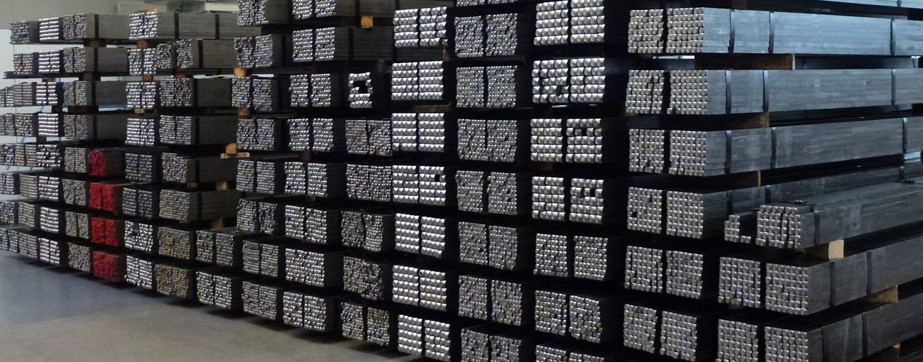
mbo Osswald has comprehensive expertise in handling a wide range of materials. Regardless of the specific requirements and areas of application, we can manufacture components from various materials and thus cover a broad spectrum of customer needs.
Predominantly, mbo Osswald processes undercut steel for efficient series production on CNC turning machines (e.g. 1.0715, 1.0718); lead-free grades compliant with RoHS/REACH for high productivity and excellent surface quality are also available. For corrosion-exposed applications, stainless steels in A2 quality (e.g. 1.4301, 1.4305) with good formability and stainless steels in A4 quality (e.g. 1.4404) with added molybdenum for increased resistance to chlorides are used. In addition, mbo Osswald offers special/specialty steels such as ETG 88 and ETG 100 for increased strength or temperature requirements, including seawater-resistant, heat-resistant or high-strength variants – optimally stocked and machined precisely from bar stock.
Variety of materials
1. Undercut steel
Undercut steel
For series production on CNC lathes, undercut steel is ideal, as it is valued for its excellent machinability. It is a special type of carbon steel that often contains additives such as sulfur or phosphorus, which facilitate chip formation and improve the quality of the end product.
Typical materials in the area of undercut steel processed by mbo Osswald: 1.0715 (11SMn30), 1.0718 (11SMnPb30)
Important properties of undercut steel:
- Excellent machinability:
Automatenstahl is specifically designed for efficient use in high-speed machining on CNC lathes. The alloying elements promote uniform chip formation, which reduces machining time and extends tool life.
- Mechanical properties:
It offers a good combination of strength and hardness, making it suitable for numerous standard applications. However, its corrosion resistance is limited compared with stainless steels.
- Cost-effectiveness:
Thanks to the improved machinability, the production of components in large quantities can be carried out more cost-effectively. This makes automatic-machine steel particularly attractive for series production.
- Lead-free:
Lead-free undercut steel is an environmentally friendly steel developed without lead and compliant with strict environmental and health regulations, such as the EU RoHS and REACH directives. Instead of lead, these steels contain alloying elements such as sulfur, phosphorus, tellurium, bismuth or calcium, which improve machinability and ensure good surface quality. They are specially optimized for high-speed machining, offer high productivity and enable efficient production with automated turning and milling machines. These steels are characterized by a good combination of machinability, surface quality and mechanical properties. To achieve optimal workability, adjustments in machining processes or tooling may be required, as machinability can vary depending on the alloy used.
- Possible applications:
Undercut steel is often used in:
- Automotive engineering: For the production of components such as screws, bolts and other fasteners.
- Mechanical engineering: In the manufacture of shafts, gears and other mechanical parts.
- Electrical engineering: For various small components where precision is important.
- Restrictions:
Undercut steel is not suitable for applications in corrosive environments, as it lacks the corrosion resistance of alloyed steels such as stainless steel. It is also less suitable for high-temperature conditions, since its properties can deteriorate at extreme temperatures.
In summary, undercut steel is the ideal choice for industrial applications where high production rates and precise dimensions are required, especially in less corrosive environments. It is an indispensable material in the mass production of mechanical components.
- Excellent machinability:
2. Stainless steel A2 quality
Stainless steel A2 quality
Stainless steel A2 quality is a designation for non-rusting stainless steel, which is particularly known for its good corrosion resistance and high strength. Technically, A2 stainless steel is an alloy based on chromium and nickel that belongs to the austenitic steels. It is often also referred to as 18/8 stainless steel, which indicates its typical chromium (approx. 18%) and nickel content (approx. 8%).
Typical materials in the stainless steel A2 quality range that mbo Osswald processes: 1.4301 (X5CrNi18-10), 1.4305 (X8CrNiS18-9)
Important properties of stainless steel A2 quality:
- Corrosion resistance:
Stainless steel A2 quality has high resistance to corrosion in normal atmospheric conditions and non-aggressive environments. This makes it ideal for applications where moisture and exposure to oxygen are present, such as in construction and the automotive industry.
- Mechanical properties:
It offers a good combination of toughness and strength, allowing it to be used in various mechanical applications. Stainless steel A2 is easily formable and has excellent weldability.
- Temperature resistance:
Stainless steel A2 quality can be used over a wide temperature range and maintains stability at both low and elevated temperatures.
- Processing:
This stainless steel is easy to work and form, which makes its use in the production of various components and assemblies easier.
- Possible applications:
Stainless steel A2 quality is widely used in:
- Food industry: Due to its hygienic properties and resistance to mild cleaning agents.
- Construction: For architectural elements, railings and facades.
- Mechanical engineering: For parts that are prone to corrosion in ambient air.
- Restrictions:
Although stainless steel A2 quality performs excellently in many areas, it is not resistant to chlorides and seawater. For environments with a high chloride content or direct contact with seawater, A4-grade stainless steel is the better choice, as it contains molybdenum, which increases resistance to such conditions.
In summary, stainless steel A2 quality offers a balanced combination of corrosion resistance and mechanical strength, making it ideally suited for a wide range of industrial and construction applications.
- Corrosion resistance:
3. Stainless steel A4 quality
Stainless steel A4 quality
Stainless steel A4 quality is a designation for stainless steel that is particularly known for its excellent corrosion resistance and chemical resistance. This type belongs to the austenitic stainless steels and contains chromium, nickel and molybdenum, which increases its resistance especially to chlorides and aggressive chemicals.
Typical materials in the stainless steel A4 quality range that mbo Osswald processes: 1.4404 (X2CrNiMo17-12-2)
Important properties of stainless steel A4 quality:
- Outstanding corrosion resistance:
Stainless steel A4 quality is particularly resistant to pitting corrosion and stress corrosion cracking. These properties make it ideal for use in demanding environments, especially in salt‑laden or chemically aggressive environments.
- Mechanical properties:
It has high strength and toughness, similar to A2 steels, but the molybdenum provides better protection in aggressive environments. Despite its hardness, A4 stainless steel is easy to form and weld.
- Temperature resistance:
Like A2, A4 stainless steel also remains resistant over a wide temperature range and exhibits high stability at both low and high temperatures.
- Processing:
The material is well suited to various processing methods, which facilitates its processing in industrial production.
- Possible applications:
Stainless steel A4 quality is frequently used in:
- Maritime industry: For parts on ships, yachts and offshore installations.
- Chemical industry: In plants and equipment that process aggressive chemicals.
- Medical devices: Because of its skin compatibility and resistance to all common disinfectants.
- Special advantages:
Thanks to its molybdenum content, stainless steel A4 quality offers increased corrosion resistance in chloride-containing and highly demanding environments, which often makes it a preferred choice over A2 stainless steel when these properties matter.
Stainless steel A4 quality therefore provides a first-class solution for applications in which both high mechanical loads and extremely corrosive conditions are present. Its exceptional properties make it indispensable in areas where safety, durability and reliability are of the highest priority.
- Outstanding corrosion resistance:
4. Other steels - "Special steels / specialty steels"
Other steels - "Special steels / specialty steels"
In addition to the materials just mentioned, mbo Osswald offers a wide range of steels that provide specific properties for different applications.
Typical materials in the "special steels / specialty steels" category that mbo Osswald processes: ETG 88, ETG 100
Examples and properties of additional steels:
- Structural steel:
A group of steel grades that are used primarily in construction for the manufacture of load-bearing structures, building components and infrastructure. Structural steel is a steel with a low carbon content (approx. 0.1% to 0.25%), which often contains small amounts of alloying elements such as manganese and silicon to improve weldability and formability. It has a ferritic–pearlitic microstructure that provides a balanced combination of tensile strength and ductility. They are available in different strength classes and are frequently used for applications where static loads occur. Structural steel is usually unalloyed or low-alloy, which makes it economical and versatile.
- Corrosion-resistant steel:
This steel is optimal for use in aggressive environments where conventional metals would rust too quickly. Such steels are ideal for applications in wastewater treatment plants, chemical processing industries, and for exterior parts of buildings.
- Seawater-resistant steel:
It is resistant to saltwater and therefore perfectly suited for use in coastal regions and for maritime structures. It is also used in the manufacture of yachts, tanks and underwater pipelines.
- High-temperature steel:
High-temperature steel is perfect for high-temperature applications such as in power plants, boilers, and furnaces. These steels retain their strength at high temperatures and minimize the risk of deformation or structural weaknesses.
- High-strength steel:
High-strength steel is ideal for heavy loads, such as those encountered in the construction of bridges, skyscrapers and heavy machinery applications. These steels provide high load-bearing capacity and are tough enough to withstand significant mechanical stresses.
- Structural steel: